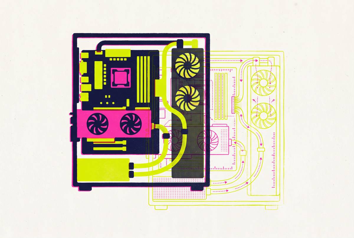
Real-Time Compatibility Engines Behind the Build Planning UI
They work best when the database tracks every part relationship across the whole build.
Real-time compatibility engines behind a build planning UI work best when they treat the PC as one connected system. When a component changes, every selection that depends on it must be checked again. That explains both their strength and their limits. They can catch compound conflicts, but only when the database describes the parts accurately and the model includes the conditions that make them work together.
Why independent compatibility checks fail compound builds
Changing the CPU can force a motherboard change, which forces a RAM generation change, which changes total power draw and invalidates the PSU selection. The CPU swap starts the chain, but the consequences reach parts the builder may have selected much earlier. Those earlier approvals are now out of date. A checker that tested each part only when it was added can leave every selection marked as valid even though the current combination no longer works.
The flaw is treating connected rules as independent decisions. Checking the CPU socket, RAM type and PSU wattage separately does not establish that all three checks remain true after a change. PC BuildIT's engineering writeup describes this as a false positive, where a build passes every individual check but remains internally inconsistent.
How constraint propagation models a build as a connected graph
Constraint propagation treats each component slot as connected to the slots whose requirements it affects. Each part has typed attributes, meaning specific fields such as socket, memory type, dimensions, TDP and connector counts. These fields do more than describe the product. They set conditions that other selections must meet. When a part changes, those conditions spread through the connected slots and the engine recomputes the build state.
The writeup describes an implementation that propagates constraints to every other slot whenever a component is added. The simulator recomputes the whole build on every change. That is what makes the checking real-time.
The relationships range from simple matches to conditional limits. A CPU socket must match the motherboard socket, while chipset support may depend on a BIOS update for newer CPU steppings. RAM generation must match the board's memory type. The GPU length must fit within the case's clearance, and the cooler height and radiator size must fit within the space each has. A match in one field does not excuse a conflict in another.
The PSU needs the right form factor, enough wattage headroom and enough available cables for the CPU and GPU power connectors. Storage checks must cover which M.2 and SATA slots are available and whether slot sharing causes conflicts. Counting slots alone is not enough here. The engine must represent the conditions under which those slots remain usable.
Where the constraint model breaks down with PSU estimation and physical clearance
Power estimation exposes the gap between a clean database field and a messy physical system. TDP is not power draw, and manufacturers use different definitions and labels, including NVIDIA's TGP, AMD's TBP and Intel's PBP/MTP. Those figures are not interchangeable measures of peak demand. Modern GPUs can also have transient spikes well above sustained draw. A wattage check based on manufacturer TDP figures without a headroom buffer gives a false green light.
Physical clearance has a similar input problem. Cooler height, RAM height beneath cooler overhang, and radiator thickness relative to fan mount depth may be absent or inconsistently reported. The engine cannot resolve dimensions it does not know. Some tools acknowledge that gap, while a silent omission can make an incomplete check look like a successful one. The distinction is important because an unchecked fit is not a confirmed fit.
A motherboard specification can state that using one M.2 slot disables certain SATA ports, giving the engine a condition it can encode. To tell whether a 165mm cooler fits a given case, the engine needs the correct measurements for both parts. The calculation itself may be simple. The missing measurement, rather than the propagation logic, is what stops the engine from giving a dependable answer.
The BIOS and firmware edge cases that slip through even careful engines
A motherboard can have the correct socket for a CPU and still need a BIOS update before the system will boot. All the hardware attributes may match, but the software on the board still does not support the processor. This is conditional compatibility. A parts database can describe which BIOS version supports a CPU, but it cannot fully establish whether that update has been applied to the physical board the builder receives.
That condition can leave the builder unable to perform the required update. AMD's official support page describes how users can lack a processor that works with their motherboard's current BIOS. The update is needed to use the new CPU, but loading it can depend on access to an older compatible one. A socket-only check misses that dependency entirely. Its answer is incomplete precisely where the builder needs practical information.
A better model keeps track of the minimum BIOS versions for each CPU and checks more than the socket alone. It can then flag the update requirement. The installed version remains a separate fact to establish.
The second tier of bottleneck detection as a different kind of constraint
Once the parts can work together, the next question is whether they will work well together. An entry-level CPU paired with a high-end GPU can pass every hardware compatibility check and still hold back the graphics card. Nothing has the wrong socket or connector. The restriction is performance, because the processor cannot keep the GPU fed at the intended resolution and frame rate.
Bottleneck detection extends the connected model into that performance relationship. Instead of matching typed hardware attributes, it compares performance envelopes, meaning what each component can deliver relative to the rest of the build. A change to the CPU or GPU therefore changes the balance that needs evaluation. The propagation idea remains useful, but it needs richer inputs than a compatibility rule.
The reverse pairing also exposes the limits of pass/fail checking. A powerful CPU with a budget GPU can be compatible without being balanced for the intended use. Hardware matching cannot identify that imbalance on its own. A performance layer shows when parts will work less well together while making clear that the build can still run.
FPS estimation and the epistemic limits of pre-build performance modeling
Pre-build FPS estimates take that performance model further by giving ranges to plan with before there is a system to measure. Their inputs include CPU and GPU positions on a normalized performance scale, resolution, quality settings, memory capacity and a game-specific reference profile. These are available before the system exists. They can help show whether a GPU suits a target resolution, but they cannot show exactly how the finished machine will behave.
The missing conditions are not minor details. The driver state, thermal headroom, load from background software and game's patch state can all change the frame rates the machine delivers. So can the memory timing behavior of a particular kit on a particular board. A normalized model does not know those conditions for an unbuilt system. Presenting its output as a benchmark would present a forecast as an observed result.
The useful output is therefore an uncertainty range. Clear communication is part of the tool's accuracy. A builder who understands the range gets a planning signal, while one encouraged to expect a guaranteed frame rate is being given the wrong basis for judging the result.
What 3D visualization adds to constraint propagation that flat rule outputs cannot
Three-dimensional visualization complements constraint propagation by showing spatial relationships that flat attribute checks struggle to express. A rule can compare GPU length with a case limit, but a rendered build can show how components occupy the surrounding space. Large coolers and tall RAM can get in each other's way. Radiators and their mounting areas do too, making the relationship between parts as useful to inspect as each part's stated dimensions.
A 165mm cooler rendered inside a mid-tower case gives the builder a way to inspect clearance visually, provided the model represents the parts accurately. That qualification keeps the visual layer honest.
Fan orientation and airflow paths add another useful planning view. A builder can see intake and exhaust placement relative to the case layout. This is not a temperature simulation, however. Like a pre-build FPS range, this view helps with planning while leaving temperatures to be measured on the finished machine.
Why data quality in the parts database determines what any engine can actually catch
Both the rule engine and the visual model need records that describe the components correctly. Even sophisticated logic can spread an error in a socket field to every check that depends on the field. The answer may look exact even though it starts from a wrong fact, so the database has to be right for the engine to work.
The writeup reports that the scraped dataset contained a meaningful proportion of bad rows, including wrong sockets, mismatched memory generations and duplicate entries with different capitalization. Every bad row gave the user a wrong answer. These defects directly change compatibility results. A wrong socket can admit an incompatible combination or reject a valid one, while DDR4 parts tagged as DDR5 can create false signals across an entire platform.
Other defects make the checking incomplete or inconsistent. Missing dimensions can leave a clearance constraint unable to fire, giving the builder no warning about the unresolved fit. Duplicate entries with different attribute values can make the result depend on which record the engine reads. The same selection can then produce conflicting answers. Neither problem is solved by adding more relationships to the model.
An open, community-maintained parts database changes how those defects can be corrected. Many contributors can identify discrepancies instead of leaving every correction to a single curation team. That distributes the work across the builders encountering the parts.
Where compound incompatibilities still slip through and what builders should verify manually
Even a well-designed engine with clean data has a boundary. It cannot fully check conditions outside its database or combinations involving variables it does not model. Small-form-factor builds make that boundary concrete. An ITX case may technically support a GPU's length only after a drive cage is removed, while tall RAM can conflict with low-profile cooler fins despite otherwise compatible specifications.
M.2 lane-sharing with SATA ports can depend on the board revision, and radiator and fan mount tolerances can change between case revisions listed under the same model name. Those are differences that the database must represent before the engine can act on them.
The practical lesson for builders is to verify those remaining conditions against manufacturer QVLs and spec sheets. BIOS update requirements, tight physical clearances, slot-sharing rules and revision-specific mount conflicts deserve that final spot-check. Explicit limits make the tool more useful. Discovering an unmentioned condition at first boot does more damage to confidence than seeing it flagged during planning.
The strongest workflow uses three layers of verification. The constraint engine narrows the choices and catches the large majority of incompatibilities, including many a builder could miss manually. Visual tools help show where parts clash in the assembled layout. Manual checks then cover what is left when firmware state, revisions or missing details in the records keep the engine from giving an automatic answer.